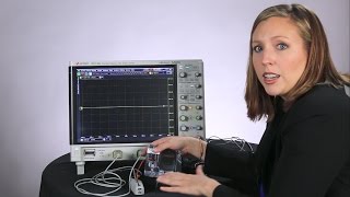
 Hi, I'm Melissa at Keysight Technologies as today's design move more and more towards battery-powered devices like smartphones, tablets, and other handhelds, I thought it would be useful to show how you can make current consumption measurements on your designs when looking for small current signals. Here I've got my battery powered device which in this case is a cellphone and to make the current consumption measurement I want to use this high sensitivity current probe and high signal integrity oscilloscope. The probe I'm using today comes with a handful of these make-before-break connectors. You can see I already have one installed in my circuit here.
So i'm going to add this make-before-break receptacle on to those test points and this just lets me easily connect to my probe tip. And what I. Really love about these make-before- break connectors is that if I have more than one test point on my board that I. Want to be looking at during testing, I don't have to resolder my probe tip connections anymore.
I can just easily disconnect from one make-before-break connector and move to another. I also have this ground connection here. I'm going to connect that to the ground lug on the probe. Now I'm going to power up my device and as that powers up I'm going to set up my oscilloscope.
So I'm going to turn on two grids and turn on channel 2 I'm going to move channel 2 into the second grid here and I'm also going to turn on roll mode so I'm going to go to set up and acquisition. And what roll does, is it turns off any triggering and it just displays the data of the waveform from right to left on the screen. So I've got that turned on now and the reason why I put up two grids here for channel one and channel two is because the probe I'm using has two different amplifiers so that we can see multiple views of the waveform. On channel 2 here, this is the zoomed out view.
This is going to be the view that I'll use to view the whole waveform at once and to catch any large current signals. For example if I were to press a button on the phone or answer a phone call I would see a larger current spike here and that's what I use channel 2 for zoomed out view. Then I have channel 1 which is the zoomed in view and this will let us zoom in onto the signal to see the small signal currents that might be hidden when you have those large signal packets when you're in the zoomed out view. We'd used this, for example, when my cell phone is an idle mode it's only going to be sending out very small current packets to check in with the cell tower or to wait for more information.
So let's go ahead and scale up these waveforms. I'm going to go to one second per division and on my zoomed-in view. I'm going to go down to 20 milliamps per division. I'm going to pull this down so we can see the whole waveform on screen here, maybe a little further, and then on channel 2 I'm going to go to about a hundred milliamps per division.
This red box here shows the portion of the zoomed out waveform that we're zooming in on up here. Now it looks like we're in idle mode and we're getting a small current packet about every second so I'm going to go ahead and stop the acquisition and I'm going to zoom in on one of these packets Alright, so now that I have one of these packets on screen, I'm going to add my current consumption measurement. So I go to measure, add measurement, I'm going to choose mixed and charge and that's on channel one and i'm going to click ok. Now we can see that on this signal we've got about 27 nanoamp-hours and now that we know how to make these measurements we can characterize our devices and we can make sure we're meeting specification.
The probe I'm using in today's video is the N2820A. High sensitivity current probe and I'm using that with the S-series oscilloscope. If you enjoyed today's video please like, share, and subscribe to the Keysight Oscilloscope YouTube channel and if there are any other topics that you'd like us to discuss please leave those in the comments below.
Labels:
CURRENT
Thanks for reading How to Make High Sensitivity Current Measurements. Please share...!

0 Comment for "How to Make High Sensitivity Current Measurements"